|
Products
and
Solutions
for:


| |
PVS-100 utilizes the EPIX PIXCI™-SV5 solution for
Analog Sensors
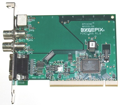
PVS-100 Standard Configuration incorporates the EPIX PIXCI™-SV5 imaging board
(SV5 Rev 1.0 shown).
Video Capture for the PCI Bus
The PIXCI-SV5 imaging board, for the PCI bus, is designed to take
advantage of the power of the host computer. Applications once restricted by limited
memory or processing power can now be easily accomplished with the PIXCI-SV5 imaging board
and a compatible PCI computer.
ACQUISITION -- A unique digital genlock circuit ensures precise
synchronization of every image. The PIXCI-SV5 imaging board automatically recognizes
unstable signals (for example, from a VCR) and adapts its locking mechanism to accommodate
the source.
A video input multiplexer allows software selection from two BNC and one S-Video input.
Programmable gain, hue, brightness, saturation, and contrast adjustments condition
the video signal.
Image sequences may be transferred at full or reduced frame rates to the PCI bus for
storage in the host computer's memory, or passed to other devices on the PCI bus such as
disk controllers or VGA adapters.
SCALING AND CROPPING -- The window of video to be captured may be
cropped in single pixel increments, then scaled in ratios from 1:1 to 1:14, down to as few
as 4 pixels by 1 line of image data. Horizontal and vertical scaling is performed in
real-time by interpolation, providing an accurate representation of the original image.
DISPLAY -- Depending on the computer's VGA adapter, 24 bit RGB color
images or 8 bit monochrome images may be displayed. The full, scaled, or cropped
image may be placed anywhere on the VGA screen. Luminance or monochrome image
data can be passed directly to the VGA for live video-in-a-window display. Color images
are normally stored in the host computer's memory, converted into RGB data, then displayed
on the VGA adapter. With a fast processor, fast PCI bus, and fast VGA adapter, live
color image data may be displayed. If the VGA adapter can accept Y/C color pixels,
images can be sent from the PIXCI-SV4 to the VGA adapter across the PCI bus.
TRANSFER RATES -- The PIXCI-SV4 imaging board is designed to use the
132 Mbytes/sec burst mode transfer rate of the PCI bus. As a bus master, the PIXCI-SV4
imaging board sends image data to the PCI bus; it does not wait for the computer's CPU to
read images from the board into PC memory.
I/O CONTROL -- Four input and four output TTL trigger signals are
available for synchronization with external events right on the imaging board.
Special Features:
- Compact PCI Board
- Supports multiple video formats (NTSC, RS-170, CCIR, PAL)
- Window NT Plug 'N Play operation
- PCI Bus Mater
- Real-Time transfer to PCI Bus
Features
MUX -- The multiplexer selects the video source
for the Programmable Gain from either the S-Video input connector or from the composite
video source on the BNC connector. The multiplexer may be switched during vertical
blanking.
Programmable Gain -- Compensates for reduced amplitude in the analog
signal input. Gain can be programmed from O% to more than 200%.
Luminance A/D -- Provides analog to digital conversion of NTSC,
RS-170, CCIR, PAL, and the luminance (Y) component of S-Video sources.
Chrominance (Color) A/D -- Provides analog to digital conversion of
the color (C) component of S-Video.
Decoder -- Separates the Y/C components. Generates the U/V color
difference signals.
Digital Genlock -- Automatic synchronization circuitry for precise
digitization. Accommodates video sources which have variable periods, such as video tape
recorders. Generates the pixel clock for transferring image data to the PCI bus interface.
Scaling, Clopping -- Interpolation is used to scale images to 1/14 of
their original size.
Temporal Scaling -- Image sequences may be captured at full or reduced
frame rates.
Trigger I/O -- Four input and four output TTL triggers can be used for
synchronization with external events. The trigger signals are controlled by the host CPU.
Specifications
(Click here to see the EPIX video board image flow diagram.)
CONNECTIONS:
- 4 Pin DIN: S-Video Input
- Two BNC-Jacks: Composite Video Inputs
- DB15: TTL I/O Triggers
- Cables optional
VIDEO INPUT:
- Color or Monochrome Video Acquisition:
- S-Video, RS-170, CCIR, NTSC, PAL
- Resolution-Pixels:
- 754 x 480: RS-170, NTSC, S-Video
- 922 x 580: CCIR, PAL, S-Video
DATA FORMATS TO PCI BUS:
- Monochrome: 8 bit
- YCrCb (UYVY, YUV4:2:2): 16 bit
- RGB: 24 or 32 bit
- Capture Rate:
- 30fps: RS-170, NTSC, S-VIDEO
- 25fps:CCIR, PAL, S-VIDEO
TRANSFER RATES:
- Requires a PCI motherboard with burst mode to host memory data rates of at least 30
MB/S.
DISPLAY - Windows:
- Display resolution as per installed VGA device driver.
- A DCI compatible S/VGA adapter is required for real-time display.
DISPLAY - DOS:
- Via Standard VGA: limited to 4 bits (l6 gray levels), non real-time display.
- Via Super VGA: 8 bit, 256 gray level display.
- Color display via adapters supporting 24 bit RGB.
- S/VGA adapters must be VESA 1.0 compatible.
BUS REQUIREMENTS:
- 32 bit PCI Bus Master slot
- Power - 0.55 Amps @ +5 Volts
- Physical board size - 4.913 in, by 3.350 in.
All data provided by EPIX, Incorporated, ©1997 Epix, Inc., All Rights Reserved |