|
Products
and
Solutions
for:


| |
Vector Correlation - A Patented Approach
The vector correlation technique, as applied to
optical character recognition, was patented by Phoenix Imaging as a viable approach to
reading dot matrix characters. The technology was developed as a method to read
indent markings on metal components and is offered under the name of MTx™ , which is
short for Material Tracking. The character recognition technology used in the
MTx™ Package is protected under U.S. Patent number 5,214,719 and 5,317,652 are owned
by Phoenix Imaging. The reading of indent marks on a metal component is among the
most difficult applications in the machine vision industry. Having approached the
task of generating an OCR system for identification of indent mark symbols made most other
OCR applications appear simple.
Definition
Vector correlation refers to a technique in which symbols are
identified using a set of points in two dimensional space.
Methodology
The concept behind the vector correlation approach is a rather simple.
Consider the dot matrix symbol in Figure 6 below. The symbol "E" is generated
with a 5 x 7 dot matrix, in which the points do not touch each other. The ideal position
for the vector correlation points to identify this symbol would be centered in each point
generated by the dot matrix marking system. One of the points is selected as the home
position or origin of the vector correlation pattern. The x-y displacement from the origin
to each of the other correlation points defines a vector, thus the term vector
correlation.
Dot matrix character and a full set of vector correlation points
The vector correlation technique generates a separate
set of correlation vectors for each symbol taught. We can threshold an image so that
the desired symbols appear as binary information in the foreground. That is the
foreground information is considered to have a value of 1 and the background information
is considered to have a value of 0. The vector correlation points can be taught in
either the foreground or the background. If the symbol appears in the foreground the
points that match positions within the symbol are referred to as positive points. If
one selects the position of the positive points correctly it is usually possible to
uniquely identify the symbol. However, if several symbols have similar shapes it may
be beneficial to include negative vector correlation points. The figure above illustrates
the proper training of positive and negative vector correlation points for the symbol
"E". Notice that it is not necessary to use all of the points that
comprise a dot matrix symbol for training the vector correlation points. In fact,
the training of most symbols require less than half the number of points that are used to
generate the symbol.
The best location for the vector correlation
points depends on the symbol. However, a few general rules can be applied for the
identification of most symbols:
- The home position is typically selected at the center of the symbol;
- At a minimum, vector correlation points should be selected at the perimeter positions of
the symbol;
- Features common to multiple symbols usually do not contribute to uniqueness of the
symbol;
- The number of negative points should be kept to a minimum when applying the technology
to optical character recognition.
The Phoenix Imaging MTx™ System also allows for missing hits.
A "hit" is considered a match of a vector correlation point (either
positive or negative) with the foreground image. The percentage of hits can be
selected to allow one or more vector correlation points to be absent from the data and
still record the symbol correlation as a match. The system allows for the
independent percentage adjustment of positive and negative correlation points.
Distinct Advantages of the Technology
There are several advantages to this technology
over the other optical character recognition approaches previously mentioned. The vector
correlation approach is literally a "perfect match" for reading dot matrix
characters. When the vector correlation points are taught at the center of each dot used
to generate the dot matrix symbol, the position of the dot can vary by ˝ its diameter and
still be found. This is very important given the fact that markings generated with dot
matrix marking systems tend to drift slightly. The second advantage is that dot matrix
symbols are composed of discrete dots and the technology does not have to "knit"
the dots together in order to isolate a match. The third advantage is that missing or
extra dots will not significantly affect the reading ability of the technology. This is
especially true when the movement of dots causes displacements between the symbol
segments.
Additional tools to improve recognition accuracy
Background Normalization
All machine vision applications require a certain level of image
quality in order to perform the application reliably. Several tools have been implement in
MTx™ System to broaden the "acceptable" image quality level. Variations in
background often make it difficult to extract the desired information. We have selected
the "Background Normalization" procedure as a preferred method whenever
possible. The "background normalization" procedure smoothes the background
features using grayscale morphology functions, "maximum", "minimum"
and "subtraction". The sequence of operators depends on whether the information
that we wish to extract is dark or light with respect to the background. The grayscale
normalization performs a "max.", "min.", "sub." sequence if
the symbols are dark with respect to the background. If the symbols are light with respect
to the background the grayscale normalization uses a "min.", "max.",
"sub." sequence. The kernel size of the "max." and "min."
operators should be programmable. The kernel size will vary based on the size of the dot
matrix marks. Regardless of the sequence used, the background normalization procedure will
yield a "relative" contrast image that will emphasis the marking. The background
normalization procedure is usually not implemented on frame grabber type image processing
equipment. The procedure is requires a considerable amount of computation and would slow
the system to a crawl. The background normalization procedure is best handled on equipment
designed to perform high speed grayscale morphology operations.
Precedence
The concept of precedence is an important part of the vector
correlation technique. During the early development of the technology, circa 1988, the
technology only implemented positive correlation points. With the use of positive
correlation points it is possible to match one symbol within another symbol. Consider
Figure 10 below, the dot matrix symbols "B", "E", "F", and
"L". The symbols are arranged in the order of complexity from right to left,
right being simplest and the left being the most complex. A match for the symbol
"L" might be found in the symbols "E" and possibly "B" in
the bottom right correlation point in moved to the left slightly. The same analogous
situation is true of the symbol "F", a match for it can be found in the
"E" and possibly the "B". However, the inverse in not true, the symbol
"F" will not be found in the symbol "L", nor would the "E"
be found in the "F". Therefore, we can arrange the symbol in an increasing order
of complexity. This table of complexity, arranged from the most complex to the least
complex in referred to as the "Precedence" table. The position of a symbol in
the Precedence table determines its "Precedence Value", the higher the value the
more complex the symbol. The Precedence Value is then assigned to the "Correlation
Number" for a particular symbol.
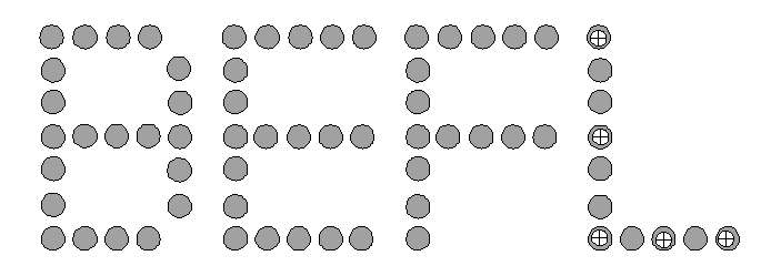
Order of symbol complexity
Symbol Spacing
Another Use important concept is that of symbol
spacing. Symbol spacing is defined as the distance in pixels from one symbol to the next
symbol. The measurement point should be consistent, either the leading edge of the symbol
or the center of the symbol. The concept of symbol spacing is used to identify whether
"white space" is present within a string of symbols. The MTx™ system also
uses the symbol spacing to determine the allowable position of symbols within the image
area. If the symbol spacing is selected at a distance of 30 pixels, only a single symbol
is allowed to be identified within that 30 pixel region. The spacing is determined by
locating the first symbol and adding symbol spacing incrementally from that position. If
for some reason more than one symbol is located within a given symbol spacing, the symbol
with the highest Precedence Value is selected.
Image Rotation
In many industrial applications the symbols are
presented to the sensor in random orientations, e.g. the axis of the symbols is not
aligned in a predefined orientation. Phoenix Imaging has found that the orientation of the
principle axis of the symbol string is good method for orientation determination. This
assumes that the symbol string is greater than two symbols in length and that a major axis
can be isolated. Using morphological techniques the principle axis of the symbol string
can be determined and then a rotation offset from a "normal" image orientation
can be applied to rotate the image. Electronic image rotation has be applied for many
years and provides the fastest for presentation of the symbol strings. Phoenix Imaging
prefers to rotate the entire image rather than small sections of the image because it
generates less "stair-step" effect. This technology is useful for identification
of symbols that a presented to the sensor in random orientations, e.g. markings on the
bottom of containers or non-oriented components on a conveyor.
OCR vs. OCV
The conceptual difference between OCR and OCV can now be
explained. In OCR applications the symbols are known but the order in which they appear in
the string is not known. In OCV applications, both the symbols and the order in which they
should appear are known.
The OCR application is more difficult to obtain reliable results than
the OCV application. The increased difficulty arises out of the uncertainty of which
symbols are allowed in which positions within the string. If the position of symbols
within the string can be assigned to particular symbol sets the read accuracy can be
improved. Often the customer has a defined arrangement of symbols within the symbol string
to identified. The MTx™ system allows the user to assign the type of symbol that can
be found in particular positions within the string. For example, the customer product code
will only allow an alphabetic symbol in the first position followed by seven numeric
symbols. In this case the allowable symbol set for the first position is includes 26
symbols. The next seven positions are then limited to symbol set of 10 symbols.
OCV applications are generally concerned with the quality of the
marking. The image processing system does not have to "read" the information in
order to determine which component is present. The system is informed of the symbols
present prior to starting the inspection. It is common for OCV applications to train
"acceptable" printed symbols as "references". The reference symbols
are then compare them to each new test image. The vector correlation technique can be used
as a method of precise symbol location and then the "reference" symbol is
compared to the test image. This technique will provide precise locations of extra or
missing print regions between the "reference" and "test" symbols.
The OCV application is easier to perform than an equivalent OCR
application for several reasons:
- The symbols are known prior to the inspection process;
- The position of each symbol is known prior to the inspection process; and
- In certain cases the symbols can be combined into a single symbol and its presence or
absence can be determined during the inspection process.
The MTx™ system allows the user to learn a symbol string as a
single set of vector correlation points. This technique is useful when the customer
does not care about the quality of the marking, but simply wants to insure that the mark
it is present.
|