|
Products
and
Solutions
for:


| |
VisionMaker™ ToolBox Components
Visual programming tools allow efficient application development
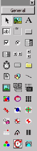
The components found in the VisionMaker™
Development Package Release 5.5 are shown in the illustration below.
Each tool has a specific purpose, however some tools may have over-lapping
functionality.
- CALIBRATION TOOL provides a method of calibrating the information
obtained by the image sensor (units = pixels) to the real world coordinates (units =
inch/mm) and vice-versa.
- MULTIPLE NORMALIZED CORRELATION (MNC) is useful to determine if a
specific component or feature is present within a specified ROI. It is different than the
(GNC) or the (GTC) in that it will identify the "best fit" correlation template
and provide the X & Y position of that match.
- AREA TOOL is used to count the number of pixels within a specified ROI.
The area tool is useful to determine whether or not a part is present. It can also be used
to determine if a feature is of a specified size.
- CENTROID TOOL is useful to determine the X & Y location of the
centroid of an object within a ROI, i.e., the first moment of a round, square, rectangular
or any shape object in the ROI.
- BLOB TOOL is used to determine a number of attributes about a blob or
several blobs within a specified ROI. The blob tool is useful to determine the shape of a
feature in the image area.
- GOLDEN TEMPLATE TOOL (GTC) is used to compare one image within a
specified ROI to another image with similar characters. The tool is primarily used to
determine whether or not a pattern in a sample image is different than that of a
pre-taught reference image.
- GRAYSCALE NORMALIZED CORRELATION TOOL (GNC) is useful to determine the
X & Y position of a component very precisely. It can also be used to determine the
offset of various inspection windows based on the position of a reference feature. The GNC
will determine the image offset to sub-pixel accuracy.
- RULER TOOL is used to determine the position of an edge and/or object
within a specified ROl window. The tool provides a number of methods to determine the
distance between points, point and line and the location of the point generated by
intersecting lines.
- BRIDGE TOOL is used to determine if material is present in a region
that it should not be located. The tool is very useful in isolating and measuring the
relative impact of solder presence between solder pads. The tool determines bridge length,
position of end points, and the size / location of islands between solder pads.
- VIEW TOOL the primary purpose of the view tool is to provide a window
in which the other tools can perform. The view tool defines an area in which the
video output from the image sensor can be displayed on the form. The View Tool or
Viewport can be thought of as a container for the other tools used in the application.
- CURVE FITTING TOOL is used to determine the best fit to an arc, ellipse,circle
or line extracted from image data. The tool can be used to accurately determine the
diameter of a circle even if a portion of the circle is obscured.
- CHORD TOOL is used to perform very fast distance or length measurements
along the X or Y axis of an image. The tool allows up to 10 times more measurements to be
made in the same time as a single edge detection tool. This is an excellent tool for the
measurement of gap or the position of object at hundreds of measurements per second.
- ROTATE TOOL is used to rotate an image an
arbitrary angle about a point. The other tools can be used to
calculate the angle and points on the fly.
New tools are constantly added to VisionMaker™ ToolBox
A Total of 13 new tools have been added to the standard VisualBasic toolbar. The arrangement of tools on tool bar
may change slightly depending on the order in which the Active-X controls are added.
Additional tools may be added for special applications, often at the request of our
customers. The toolbar will only appear during the development phase of the
project. During the development phase the user may access any of the tools
properties for calculation. After the application has been designed and tested, it
is normally built (compiled and linked) into an executable format for implementation.
In the executable form the application can not have tools added or removed.
However, tools that are present in the application can be repositioned and changed in size
as required. Even the vision algorithms associated with a tool can be changed during
run-time deployment. The vision algorithm associated with each of the tools can be
changed to meet the specific requirements of a particular application, even after
implementation in the field!
Special Features:
- Easy to use ActiveX (32 bit) tools
- Can be used in MS VisualBasic (is currently available for
32 bit
tools) or MS Visual C++ environments
- Over 150 image processing functions
- 13 tools can be combined to provide solutions to a wide range of machine vision
applications
- Pre-defined run-time "properties" panels are provided for all tools
- Each tool allows the user the option to generate their own image processing algorithm or
to use the default vision algorithm
|