A Typical VisionMaker™ ToolBox Component
ToolBox component properties can be customized
All applications begin in the development environment using
Microsoft Visual
Basic (VB) or Microsoft Visual C++ (VC++). The VisionMaker™ ToolBox components are
provided in ActiveX (32 bit) formats. These tools have been
developed and tested to insure ease of integration into machine vision applications.
Each tool has a unique purpose and allows extraction of desired information from
the image data with minimal programming. The VisionMaker™ development
environment is similar for all board sets. However, the number of functions and
function names may change slightly depending on the board set selected.
 The primary
tool used in all applications is the View tool (the icon on
the toolbar is displayed at
left). This tool has two functions: first it is used to display video information
from the sensor or working image buffer; second it is used as a
"container" in which the other ToolBox components may be used. The process
is simple, the user creates a new VB or VC++ form in the development environment.
Then the user draws a Viewport using the View tool on the form by clicking in the View
tool icon of the toolbar and dragging it on to the form. The Viewport is sized the
meet customer requirements. The primary
tool used in all applications is the View tool (the icon on
the toolbar is displayed at
left). This tool has two functions: first it is used to display video information
from the sensor or working image buffer; second it is used as a
"container" in which the other ToolBox components may be used. The process
is simple, the user creates a new VB or VC++ form in the development environment.
Then the user draws a Viewport using the View tool on the form by clicking in the View
tool icon of the toolbar and dragging it on to the form. The Viewport is sized the
meet customer requirements.
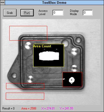
The example at the left illustrates the Viewport (image
area) with several ToolBox components positioned above the part to be inspected.
There are two tools that are activated, the region within the bounding box has
had some type of image processing performed. The region highlighted in
yellow, indicating the currently selected tool, is the Area tool. The
region in the lower right of the image
is the Centroid tool. The other tools have been placed on the Viewport but are not
currently active.
The outline of the tool regions are displayed in red.
They maybe resized during run-time by simply clicking on a tool and repositioning a
corner. The display of each tool's image processing operation can be selected within
the vision algorithm. When cycle time is critical it is better to limit the number
of displays used.
 Each
tool has a unique complete set of properties associated with it. The number of
properties depends on the complexity of tool. The Area tool is one of the simplest
tools in the ToolBox, its icon as found on the toolbar is shown at the left. The
purpose of the Area tool is to determine the number of pixels within a user defined region
of interest (ROI). The area count determined by the Area tool is made available for
use in VB or VC++ by the "Nominal" variable. Each
tool has a unique complete set of properties associated with it. The number of
properties depends on the complexity of tool. The Area tool is one of the simplest
tools in the ToolBox, its icon as found on the toolbar is shown at the left. The
purpose of the Area tool is to determine the number of pixels within a user defined region
of interest (ROI). The area count determined by the Area tool is made available for
use in VB or VC++ by the "Nominal" variable.
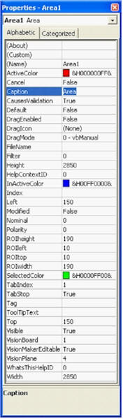
The properties form displayed during the development
phase for the Area tool is shown at the left. The name "Area1" is
automatically assigned to the first Area tool. The next occurrence of the Area tool
will be labeled "Area2", the next "Area3" and so forth. The name
of this or any other tool can be changed to describe the user's inspection task by editing
the property "Name". By accessing the property "Nominal", the
user can obtain the number of pixels within the ROI. The property
"Polarity" is used to select whether the object is lighter or darker than the
background when using the default vision algorithm.
The panel shown on the right is the
"properties panel" as displayed when
running. The "Polarity" is selected using a radio button.
All of the ToolBox components have a development and a run-time version of the
properties panels. The number of properties that a components has is determined by
the complexity of the tool. All of the components found in the VisionMaker™
ToolBox offer the VisionMaker™ vision
editor, a Phoenix Imaging exclusive. This unique tool allows the user
to generate their own vision algorithm for any tool. When selected the tool foregoes
the default vision algorithm and uses a vision algorithm as defined in the
VisionMaker™ vision editor. Each tool can have a unique VisionMaker™
vision algorithm.
VisionMaker™ vision editor
The VisionMaker™ vision editor allows the user to generate
vision algorithms using all of the functions in the library. This product
was originally designed to speed internal vision algorithm development. It
has evolved into a priceless tool for the migration from lab to plant floor.
The VisionMaker™ vision editor allows the developer to evaluate the algorithm
real-time and make modifications as required.
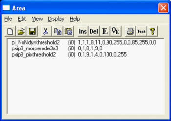
The VisionMaker™ vision editor
generates a list of user selected functions. The functions are executed
from the top of the list to bottom each time the tool is called. The
flexibility of the vision editor is that you "see" the result of parameters
being changed immediately on the video display. There is no maximum size
to the the algorithm. The number of image buffers is limited only by the
amount of memory in the system. The typical configuration has either 1GB
(small sensors) or 2 GB (large sensors) of system memory. Windows XP Pro
allows up to half of the system memory to be assigned to the image buffers.
|